- Caractéristiques des candélabres :
- Hauteurs : de 25 à 40 m.
- Effort en tête : de 8 à 40 kN.
- Section pleine en tête avec surface plate et perçages de fixation des consoles support de lisolant et des câbles.
- Section intérieure évidée.
- Jonction mécanique boulonnée entre tronçons à réaliser sur chantier.
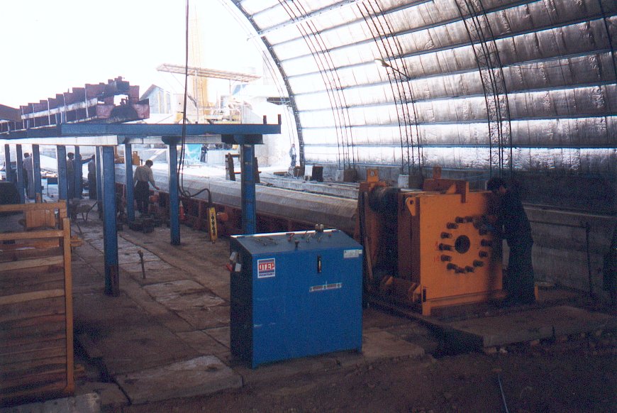
- Ligne de production par tronçon comprenant :
- 1 moule polyvalent en deux coquilles : 1 coquille inférieure et 1 coquille supérieure manutentionnable à laide dun palonnier. Jonction étanche entre les coquilles par plats usinés et joint caoutchouc.
- 2 poteaux en acier et 1 tête de tension 800 T fixe avec plaque dancrage des armatures percée pour le passage du noyau central.
- 2 poteaux en acier et 1 tête de tension 800 T mobile pour la détension des armatures (lente et globale, ossature et 4 vérins hydrauliques fixes pilotés par une centrale de détension.
- 1 système daccrochage de la bride de jonction par tirants dancrage (acier à très forte résistance).
- 1 noyau central métallique avec embouts interchangeables (selon leffort du poteau) et système dextraction dès le début de la prise du béton.
- 1 lot dancrage des armatures.
- 1 lot de vibreurs électriques / pneumatiques.
- Commun aux 2 moules :
- 1 vérin hydraulique de tension des armatures de précontrainte avec pompe hydraulique mobile et nez rallongé.
- 1 machine à matricer les aciers de précontrainte pour laccrochage dans la bride de jonction (continuité de la précontrainte).
- Option : traitement thermique électrique régulé.
- Option : bâche et dérouleur de bâche.
- Option : trémie de coulage du béton.
- Lingénierie complète est également fournie avec cette ligne comprenant principalement :
- Génie civil du banc de précontrainte.
- Plans dexécution et notes de calcul des poteaux.
- Spécifications techniques des accessoires (échelles, mise à la terre, consoles,
).
- Formation pour personnel détudes et de production.
|
- Characteristics of lighting poles:
- Heights: from 25 to 40 m
- Top effort : from 8 to 40 kN
- Plain full concrete section at the top with flats surfaces for the fixing of the arms supporting the insulating devices and the cables.
- Voided inner section of pole.
- Mechanical connecting splice between upper and lower member to be bolted on site.
- Complete line including for each member:
- 1 polyvalent mould made with 2 shells: 1 lower shell and 1 upper shell movable with lifting beams and over-head crane. Concrete-proof junction between shells made with machined flat profiles and rubber joint.
- 2 steel columns and 1 tensioning head 800 T for the anchorage of the armatures voided for the taking out of the central core.
- 2 steel columns and 1 mobile head 800 T for the releasing (smooth and global) of the armatures, solid main frame and 4 hydraulic jacks driven by hydraulic detensionning pump.
- 1 holding device for the connecting splice by pulling rods (very high grade steel).
- 1 metallic central core with changeable ends (according to strength of pole) and its extracting system as soon as the concrete starts to harden.
- 1 set of anchorages for the armatures.
- 1 set of electrical / pneumatic vibrators.
- Common for 2 moulds :
- 1 tensioning hydraulic jack for the prestressing armatures with mobile hydraulic pump.
- 1 threading machine to prepare the ends of prestressing steels for anchorage to the connecting splice (continuity of prestressing).
- Option: automatic electrical heating system.
- Option: cover and its uncoiler.
- Option: concrete hopper.
- Full engineering is also provided along with this line, including the main following items:
- Civil works for prestressing bed.
- Shop drawings of the poles with design notes.
- Technical specifications for accessories (ladder, earthing system, arms, ...).
- Teaching for design and production.
|